Welcome
to the
Super
Nintendo ( SNES ) controller to Parallel Port ( DB-25 ) adapter
Building Instructions Page
How to Connect your Super Nintendo Controller to your
PC.
Why? I Started this because I wanted to have the real feeling (heh,
yeah)
when playing SNES games on my PC.
The instructions on the internet are available but very scattered, and
some are actually wrong (like having the SNES pins reversed). Basically
I spent a day or so putting info together and took the plunge to see if
everything would work. Why did I make this page? *SHRUG* I like
documenting stuff...oh and for anyone wishing to do the same too.
Note:
I started off the project
by making a breadboard prototype, you may skip this step if you wish. I
did it because I wanted to make 100% sure it would work on each of my
machines. Your results may vary, I do not guarantee anything you see
here. Please take great care when working with hot/sharp tools.
Finally, this was a learning process for me, so if I forgot to document
one or more steps thats probably because I forgot them as I wrote this
page AFTER I completed the project. If you find this useful, enjoy! If
not, stop wasting my bandwidth..heh...
Stuff Needed:
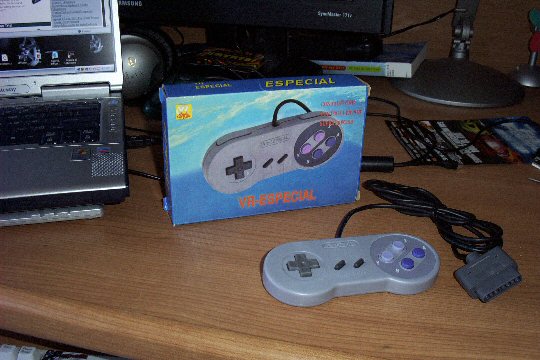
1 SNES Pad
5 diodes (Radio Shack part #1N914)
10 little wires.
1 DB-25 Male adapter (crimp or solder)
1 Bag of 25 male pins (the bigger ones)
1 DB-25 Shell
1 Wire stripper/crimper
1 Soldering iron
Time, and some other stuff I might be forgetting.
Construction Steps:
1) Buy or take out your Super Nintendo controller.
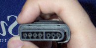
2) Here are the SNES pins: 7,6,5,4,3,2,1 <-- yep, backwards, refer
to pic.
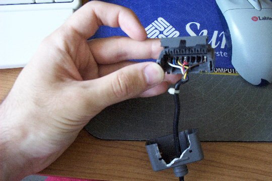
3) Some people like to cut the cable right above the connector, I
decided to go a different route since I don't plan on ever reusing the
plug. I broke open the connector and slid
out the pin-assembly. There are latches holding the assembly in there,
break off one side of the surrouding sleeve and pull out the assembly
but sticking your screwdriver between the plug assembly and surrounding
sleeve. Do this only if you
decide to follow in my footsteps and not cut the cable. Another reason I did this was to bypass the
step that requires you to use a multimeter to check each wire
inside the cable and see which pin is for which color cable. More
details below.
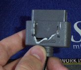
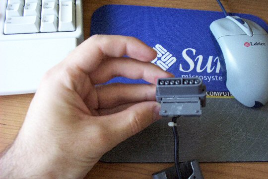
4) When you slide out the pin assembly you will need to pop open the
hood that contains the pins for the controller. Stick a very small
screwdriver into the hole as shown below and push on the screwdriver
like you were putting a spoon in your mouth.
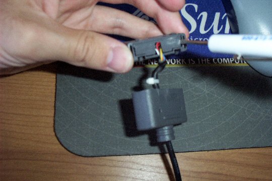
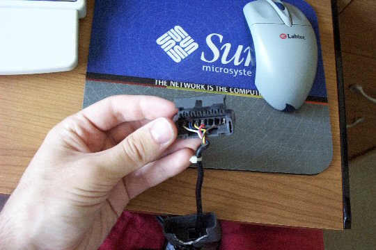
5) When the hood is propped off we get a REALLY clear view of which pin
goes to which color cable. Now you know why I went this direction ( and
the fact that I will never reuse this SNES connector again is also
related).
6) Just for reference, the snes pad tilted so you can see the pins and
relate them to the cables above.
7) Pins to wire colors for my pad (VR-ESPECIAL):
Close up:
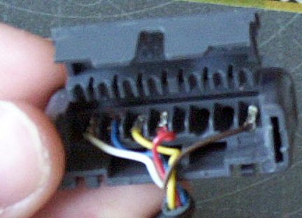
7
|
6
|
5
|
4
|
3
|
2
|
1
|
White
|
Blue
|
Yellow
|
Red
|
XX
|
XX
|
Brown
|
ATTENTION!!! When you take apart your cable, your colors may vary as
there was no
standard for SNES pad wire coloring...you have to manually check which
pin on the SNES pad is connected to which color wire! ATTENCION!!
Here is the schematic:
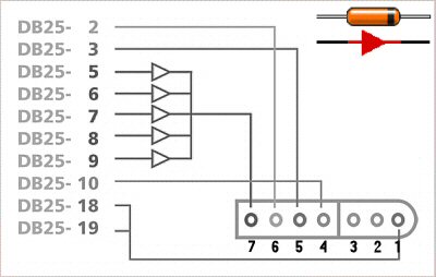
Ok, here is where you start building the prototype thing. This couldn't
be easier. I have a little electronics experience, but this is too
easy. It's just a matter of connecting the SNES Pad's wires to the
wires of your DB-25 plug. I won't go into explaining how to
strip/crimp/insert wires. The diagram is as plain as daylight. Just
plug in the corresponding wires to a row of holes on your
breadboard and connect each diode/DB-25 wire to the appropriately
colored wire's pin-hole array (EX. DB-25 Pin-2 wire goes to SNES Pin-6
wire). Sounds confusing, here is the short way: put the breadboard
horizontally on a table, plug in each SNES wire separately so that it
has it's own row of holes underneath it like this (JUST AN EXAMPLE):
Row 1 2
3 4 5
| I | |
I | | I | | I
| | I | <-- SNES
Cables
in the fist holes...damn this took a long time to make...THIS BETTER BE
USEFULL TO YOU PEOPLE.
| o |
| o | | o | | o
| | o |
| o |
| o | | o | | o
| | o |
| o |
| o | | o | | o
| | o |
| o
| | o | | o |
| o | | o |
Then plug in the appropriate Diode or DB-25 wire in the same row as the
one that has the SNES-wire. Couldn't be simpler.
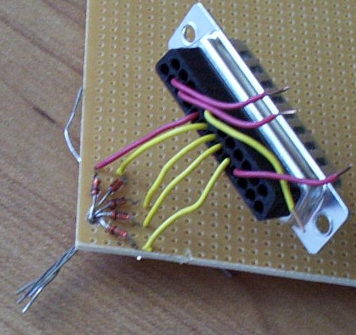
8) Here is the finished Breadboard prototype (click on the pic
to see the HUGE PIC, for clarity)
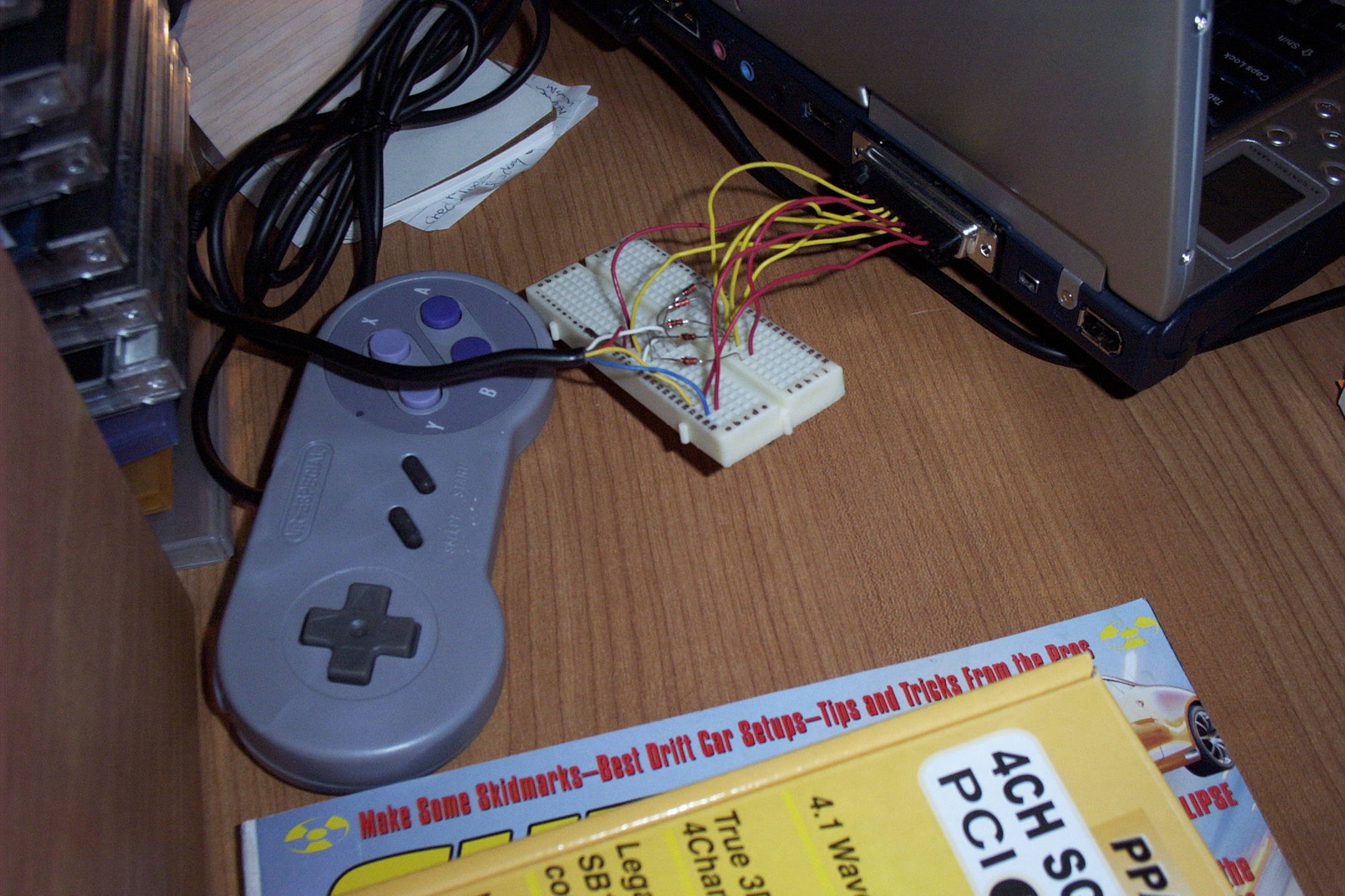
Breadboard prototype worked the first time (yippy) with only 5 diodes
(Rat Shack 1N914), not 3 and not 6 like some other people have...
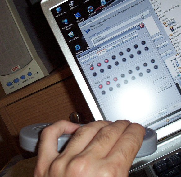
9) Here is me testing out the pad in "PSXPad"
NOTE: I dropped PSXPad for PPJoy as
PSXPad was giving me problems in emulators.
This pic (of PSXPad setup screen) is here just for show, to show that
the pad DOES work.
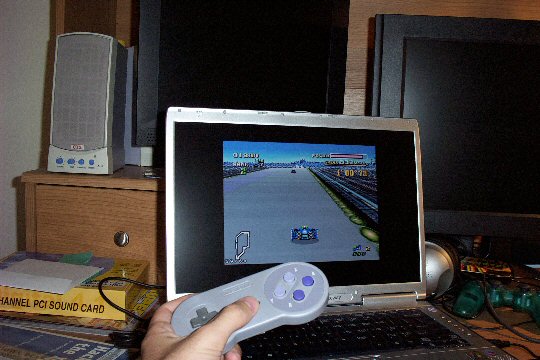
10) This is me testing out the pad with F-Zero in SNES9x in Windows
XP(SP1), using the PPJoy driver.
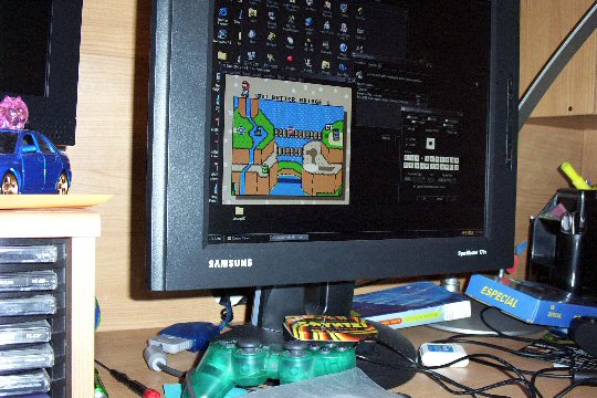
This is me testing out Super Mario All-Stars in SNES9x with DirectPad
Pro 5 on Windows 98SE.
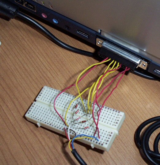
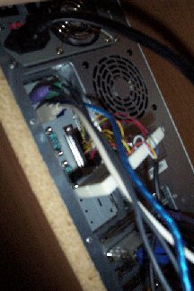
Etc) This is the breadboard hanging off a parallel port on my Win98SE
machine...testing testing testing....
Good stiff cables did the trick (since I lost my PP extension wire, I
had to do this to test).
11) Ok, here we begin the work on the final
product.
This pic shows me soldering the diodes to the wires on a protoboard.
My soldering skills need work, as does my "design technique".
You may wish to just wrap the diodes to each other and to the wires and
then solder them,
skipping my "diodes on protoboard" design.
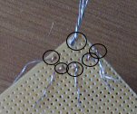
I cut the wires to half the length of the ones from the breadboard
prototype.
I spread the diodes apart enough so that they would not short each
other out,
afterwars I connected the cathode side to one hole and tied the diodes
together. ( This is the side that will give power to the SNES pad from
the Printer Port).
Here I put the wires coming from the PP connector through some holes
right next to the diodes, and soldered the diodes to the wires.
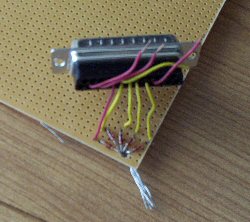
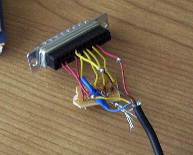
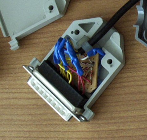
12) Ok here is the [almost] finished product.
I soldered the wires to each other and then tied the points and the
diodes with electrical tape (for safety).
This is almost the exact same process as building the breadboard, the
wires from the SNES pad go to the wires on the DB-25 adapter.
Just tie the wires to each other (by following the schematic) and
solder the connection point with a dab, try to solder it around the
connection so it almost looks like a ball. Be careful with the SNES
pad's wires as they are VERY fragile and easy to rip.
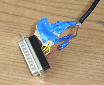
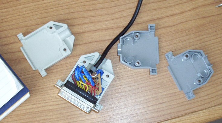
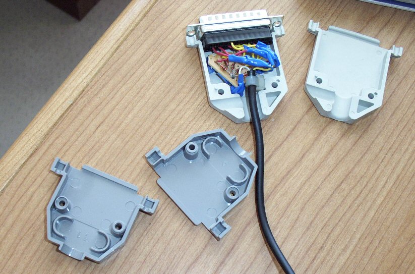
13) Here is the connector right before I closed it. Notice I am using a
shell that is bigger than standard shells.
I had to do a little work to find this, because I had to fit so much in
(with the protoboard) I couldn't use the regular
old shells that you find everywhere. It cost me $0.49 for this bigger
shell at an electronics store. Your luck may vary,
or you could just not use a protoboard and bend the diodes into the
little shell. You choice. I know my work looks messy,
but the main point is that it works. Not like I'm selling this thing.
Notice the Zip-Tie on the black cable, this is to prevent pulling
on the cable, thus preventing pulling apart the internals. Safety.
14) TADA! Final product, sexy isn't it? Almost good enough to sell on
eBay....NOT! I won't be giving up this baby for a while.
Please don't email me to make you one =/ it took me two weeks just to
get the pads and this is so easy and cheap to make that
anyone can do it.

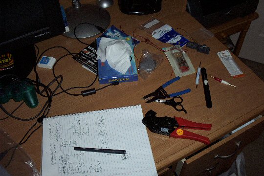
And here is a cheap shot, my workspace! There are some of the tools
you'll need.
A wire cutter, a wire stripper, a wire crimper (unless you're soldering
your stuff), pin extractor,
small flathead screwdriver. Not pictured is the soldering iron.
The End of the buildup. Questions? Email me.
Drivers and stuff that worked for ME:
Here is a little tool I found to test
your controller. This little utility is
DOS-based but will work in 98/XP because it communicates directly with
your LTP (parallel port). You have to know which I/O Range it's in, do
that by going into Device Manager, then into your Ports and Printer
Port proerties, then click on resources.
UPDATE: Might not work in XP!! Froze
for me!! BAD!
And now the drivers:
Windows
XP = PSXPad - http://www.psxpad.com/ <-- Works in
Control Panel, but chokes in emulators!!! CRIZAP!
Windows XP (SP1) = PPJoy (worked great, and the most
recently updated of all it seems) http://www.geocities.com/deonvdw/PPJoy.htm
Windows 98SE = DirectPad Pro 5
(discontinued, but works great) - http://www.zophar.com/joy.html
These drivers are the ones that worked for me (on Windows 98SE I forgot
that I turned off my LPT port so I spent a couple hours banging my head
on the table untill I remembered that little fact...), if these don't
work for you then you either put the adapter together wrong or bla bla
bla.
Total
Cost:
$10 for SNES Pad, $2 for diodes, $0.50 for DB-25 assembly,
$0.50 for DB25 shell, $1.10 for pins, etc...
* Started -
05/24/04 at 5:00pm ->
Finished - 05/24/04 at 11:30pm
(with breaks and a drive to Radio Shack)
* Started Final Assembly - 05/29/04 at 1:30pm ->
Finished - 05/29/04 at
4:50pm (before Stanley Cup Finals game...)
Page made by roto
(roto_at_mozy.org)
Last Updated: 06/19/04 (Final Update, hopefully)